Process Control
The process will be controlled independent of any high level software and hardware that may be prone to virus attacks.
The sub-systems will include various inputs and outputs to control and monitor the process. They will become active or inactive based on the phase that currently needs to be executed.
Rate Control
Where rate control is required, the following approach is used depending on what type of actuator is available:
-
On/off actuator – Pulse width modulation with configured period. Duty cycle will be calculated using a PID algorithm or using the pressure change and time as defined in the specification.
-
Continuous Flow Control – Analog value will be calculated using a PID algorithm
-
PID constants will be stored with chamber and phase type and pushed to the appropriate physical device at the beginning of a phase
-
Integral wind up will be reset at the beginning of each new phase
Manual Overrides
Some parameters may be overridden during the process to prevent deviations. Any manual changes to specification parameters will require that the user re-enters their password. Manual changes will be active for the current phase only and will be overwritten by parameters from the cycle definition following the phase transition.
Some parameters may be modified during the process to prevent deviations; the “Can Modify During Phase” column indicates which parameters are modifiable while the cycle is running that particular phase (i.e. modifiable parameters are indicated throughout section Supported Phases). Note the following restrictions on some of the modifiable parameters:
-
Jacket temperature set-point and minimum/maximum tolerance values are modifiable during all phases throughout the cycle as long as the new value lies between 32 °F and 212 °F:
-
The jacket temperature set-point must be greater than the jacket temperature minimum alarm tolerance and less than the jacket temperature maximum alarm tolerance.
-
-
Chamber temperature set-point is modifiable during all phases throughout the cycle as long as the new value lies within the chamber temperature minimum and maximum alarm tolerances and is less than the cooling temperature set-point.
-
Cooling temperature set-point is modifiable during all phases throughout the cycle as long as the new value is greater than the chamber temperature set-point and less than the chamber temperature maximum alarm tolerance.
-
The set-point “pressure increment for specified duration” is modifiable during all phases throughout the cycle as long as the new value is less than the original “pressure increment for specified duration” set-point for the phase.
-
The pressure set-point, when modifiable, can only be changed within the predefined minimum and maximum pressure alarm tolerances.
-
The duration set-point, when modifiable, can only be changed within the predefined minimum and maximum pressure alarm tolerances.
-
The “loop count” set-point, when modifiable, can only be changed so that it is greater than the set-point from the cycle definition.
Chamber Heating/Cooling Control
Parameters
The following parameters are specified in each phase and are used in the chamber heating and cooling control:
-
2 – Chamber Temperature Set-point
-
3 – Chamber Temperature Alarm Tolerance
-
4 – Chamber Temperature Warning Offset
-
6 – Jacket Temperature Set-point
-
7 – Jacket Temperature Tolerance
-
8 – Jacket Temperature Warning Offset
-
58 – Cooling Temperature Set-point
Feedback Sensors
If multiple jacket temperature elements exist then the average temperature using all enabled thermocouples will be used as the jacket temperature measured value, unless otherwise described in the HT# Template.
If multiple chamber temperature elements exist then the average temperature using all enabled thermocouples will be used as the chamber temperature measured value.
Normal Sequence Process
The temperature of chamber jacket and chamber air is maintained using two PID control loops. Control loops calculate % output which is used to control opening of proportional valves or % on cycle of block valves.
Heating
Chamber is actively heated when:
-
Jacket temperature or chamber temperature is below their respective temperature set-point [Parameters 2 and 6] AND
-
Neither jacket nor chamber temperature is higher than their respective maximum warning thresholds or alarm tolerances.
Cooling
Chamber is actively cooled when:
-
Heating PID loop calls for no heat AND
-
Chamber temperature is above the cooling temperature set-point [Parameter 58] AND
-
Neither jacket nor chamber temperature is lower than their respective minimum warning thresholds or alarm tolerances.
Dormant Sequence
-
While chamber is Dormant, temperature control of the chamber is as follows:
-
If the door closed switch is sensed, both dormant jacket [Parameter 6] as well as dormant chamber [Parameter 2] temperature set-points are used to control the chamber heat as described above
-
If the door closed switch is not sensed, only the dormant jacket temperature set-point will be used
-
If the jacket temperature is higher than the dormant jacket temperature set-point plus 5°C, heating will cease. Alternate Heating/Cooling Control, if enabled, will override this functionality.
-
Failure Modes
If all jacket thermocouples fail:
-
Chamber will enter the stop mode if there is a jacket temperature heat set-point or tolerance defined.
-
The system will raise an alarm but will continue operating if there are no jacket temperature set-points or alarm tolerances defined.
If all Chamber air thermocouples fail:
-
Chamber will enter the stop mode if there is a chamber air temperature set-point (heating or cooling) or tolerance defined
-
The system will raise an alarm but will continue operating if there are no chamber temperature set-points or alarm tolerances defined
Alternate Chamber Heating/Cooling Control
When Alternate Control is enabled, the temperature of chamber jacket and chamber air is maintained using two cascaded PID control loops. Control loops calculate % output which is used to control opening of proportional valves or % on cycle of block valves.
Parameters
The following parameters will be used in the chamber heating and cooling control:
-
2 – Chamber Temperature Set-point
-
3 – Chamber Temperature Alarm Tolerance
-
4 – Chamber Temperature Warning Offset
-
6 – Jacket Temperature Set-point
-
7 – Jacket Temperature Alarm Tolerance
-
8 – Jacket Temperature Warning Offset
-
58 – Cooling Temperature Set-point
-
1030 – Alternate Heating - Jacket Temperature Offset (Relative to Chamber)
-
1031 – Alternate Heating - Jacket Temperature Multiplier (Relative to Chamber)
Function Diagram
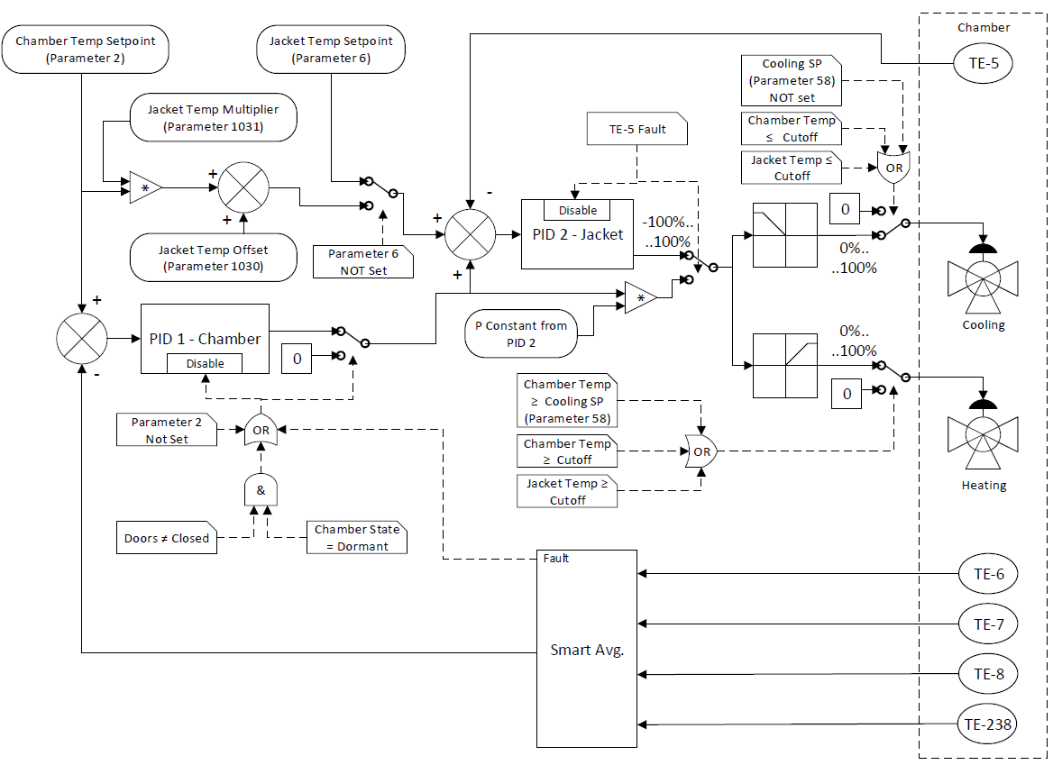
PID Loops
The output of the Chamber Heating PID loop will be determined using the following:
-
The readings from enabled and functional chamber temperature elements, as described in the configured HT template, will be used as the process value
-
The chamber temperature setpoint (Recipe Parameter 2) or, when the Chamber is Dormant, the dormant chamber temperature setpoint (General Configuration Parameter 2) will be used as the PID setpoint
-
If any of the following is true the Chamber Temperature PID will be disabled and the output of the PID will not be used by the Jacket PID:
-
All Chamber temperatures (TE-6,7,8) and Chamber monitoring temperature (TE-238) have failed or been disabled
-
Chamber temperature set point (Parameter 2) is zero (0)
-
Doors are not closed and Chamber is in dormant cycle type
-
-
The Chamber Heating PID loop will be configured to give an output range of -100% to +100%
The output of the Jacket Heating PID loop will be determined using the following:
-
The readings of the jacket temperature elements, as described in the configured HT template, will be used as the process value
-
The base setpoint for the Jacket Heating PID loop 2 will be offset by the output of the Chamber PID loop multiplied by a fixed factor (1 ÷ [percent scaling constant for chamber PID]). The base setpoint for the jacket heating PID loop 2 will be determined as follows:
-
When the cycle sequence is NOT Dormant:
-
If set, the jacket temperature setpoint (Parameter 6) from the current phase will be used
-
If Parameter 6 is not set, the chamber temperature setpoint (Parameter 2) will be multiplied by the Jacket Temperature Multiplier (Parameter 1031) and added to the Jacket Temperature Offset (Parameter 1030). This calculated value will be used in place of the jacket temperature setpoint
-
-
When the cycle sequence is Dormant:
-
If set, the dormant jacket temperature setpoint (General Configuration Parameter 6) will be used
-
If General Phase Parameter 6 is not set, the dormant chamber temperature setpoint (General Configuration Parameter 2) will be multiplied by the Jacket Temperature Multiplier (Parameter 1031) and added to the Jacket Temperature Offset (Parameter 1030). This calculated value will be used in place of the dormant jacket temperature setpoint,
-
Dormant jacket temperature setpoint,
-
-
-
If the Chamber PID is disabled then the base setpoint for the jacket PID loop will not be offset.
-
If Jacket Temperature TE-5 has failed or been disabled, the Jacket Temperature PID loop 2 will be disabled and will not be used by the Heating and cooling valves. Instead the output of the Chamber PID loop 1 will be scaled by a calculated factor ([proportional constant for jacket PID] ÷ [percent scaling constant for chamber PID] ÷ 100) and used to control the valves.
-
The Jacket Heating PID loop will be configured to give an output range of -100% to +100% where -100% to 0% will be inverted and used to control opening of cooling proportional valves or % on duty of cooling block valves and 0% to +100% will be used to control opening of heating proportional valves or % on duty of heating block valves.
Heating
Chamber will be actively heated when:
-
The output of the PID to the valves is greater than 0% AND
-
Neither jacket nor chamber temperature is higher than their respective maximum warning thresholds ([Parameter 3 – Parameter 4] and [Parameter 7 – Parameter 8]) or alarm tolerances (Parameters 3 and 7) AND
-
Chamber temperature is below the cooling set-point [Parameter 58].
Cooling
Chamber will be actively cooled when:
-
The output of the PID to the valves is less than 0% AND
-
Cooling temperature set-point [Parameter 58] is set to a value. Not setting this parameter prevents the cooling subsystem from turning on for some phases where cooling is undesirable. AND
-
Neither jacket nor chamber temperature is below their respective minimum warning thresholds ([Parameter 3 + Parameter 4] and [Parameter 7 + Parameter 8]) or alarm tolerances (Parameters 3 and 7).
Multiple Jackets
If a second jacket is used, then another two PID loops and two sets of PID constants will be added. The heat control for the second jacket will use the same parameters as the first jacket, except:
-
When the cycle sequence is NOT Dormant and Parameter 6 is not set, then the base setpoint for the jacket 2 heating PID loop 2 will be determined as follows:
-
The chamber temperature setpoint (Parameter 2) will be multiplied by the Jacket 2 Temperature Multiplier (Parameter 1033) and added to the Jacket 2 Temperature Offset (Parameter 1032).
-
-
When the cycle sequence is Dormant and General Phase Parameter 6 is not set, then the base setpoint for the jacket 2 heating PID loop 2 will be determined as follows:
-
If, the dormant chamber temperature setpoint (General Configuration Parameter 2) will be multiplied by the Jacket 2 Temperature Multiplier (Parameter 1033) and added to the Jacket 2 Temperature Offset (Parameter 1032).
-
Cold Junction Compensation Alarm
When a cold junction compensator (CJC) is wired in the module (used for temperature measurements), it can sometimes fall out of the terminal blocks causing the module to use a default value for the CJC which can in turn cause inaccurate temperature readings.
Alarm 418 will be raised when the system detects a cold junction open circuit.
Humidity Control
If the humidity sensor is present, humidity is converted from mg/l to %RH using the following exponential formula:
[100*ρ*(273.15+T)] / [1323 * e(17.3*T)/(T+238)] where:
-
ρ – density in mg/l
-
T – temperature in degrees Celsius
Clarifications for Process Control Module
The following terms must be defined for the purposes of AccuSOLO Process Control module interlocks:
|
Term |
Definition |
|---|---|
|
Chamber is Flammable |
Any time EO is admitted into the chamber. |
|
Chamber is NOT Flammable |
EO was never admitted OR Last Vacuum before final Air In-bleed has completed AND measured and calculated EO concentration is < 13.5 mg/l |
Condensation Warning
Condensation warning will be determined within the process control module function as follows:
-
RH Sensor is available:
-
Relative humidity (RH) will be calculated using the jacket temperature and the measured water vapor density
-
If the resultant RH is 99.5% or higher, an alarm will be raised
-
-
RH Sensor is not available:
-
Using the jacket temperature, saturated steam partial pressure will be looked up using the steam table
-
If the resultant partial pressure is lower than the estimated partial pressure of steam in the chamber, an alarm will be raised
-
-
When the jacket temperature is lower than the chamber temperature by a configurable amount, an alarm will be raised
-
Condensation warning algorithm will be working with a smaller partial pressure of steam after dynamic phases resulting in a reduced probability of a warning being raised if the RH sensor is not available.
EO Concentration in Continuous Steam Conditioning
At the beginning of the phase:
-
The current value of the Ethylene Oxide (EO) partial pressure is stored
-
The partial pressure of steam is changed to be the same as the pressure in the chamber in order to calculate condensation warnings and alarms.
During the phase:
-
All pressure variations will be attributed to steam.
At the end of the phase:
-
The EO partial pressure is replaced with the stored value and the remaining chamber pressure is placed in the steam partial pressure. If the chamber pressure is less than the stored EO partial pressure then the EO partial pressure will be made equal to the chamber pressure.
Timers and Timer Operation Verification
Time is critical for phase length control. There are two independent time keeping devices:
-
PLC Real Time Calendar/Clock (RTC) – Used for monitoring of the phase length.
-
PLC’s One Second “Tick” Counter – Used to control the phase length.
The PLC RTC gets synchronized with the server when any of the following takes place:
-
A load is transferred to the PLC.
-
When a PLC has been configured (administrative function typically performed by Konnexis).
-
Every 24 hours by the Buffer Service.
-
Buffer Service has restarted.
Note: PLC RTC can also be viewed on the AccuSOLO main HMI client in UTC format (time-zone independent).
Each phase length is metered by the accumulated value of the 1 second tick counter whereas the “start” and “end” of each phase will be time stamped by the real-time calendar/clock.
The Detailed Run Record report shows RTC time stamps at the start and end of a phase, as well as at predefined user configurable intervals. Each phase summary on the Detailed Run Record will show the “Elapsed In-Spec Time” value obtained using the 1 second tick counter. If the phase ran without out of specification conditions, then the time span between the start and end time stamps will equal the “In-Spec Time” +/- 0.5%.
Some exceptions may be observed when time stamps occur during daylight savings changes. The system will display time stamps which are logically correct but the time span calculated using these time stamps will be off by 60 minutes. Other discrepancies will be observed if the in-spec time was paused due to holds or out of specification conditions indicated by alarms.
Timers and Timer Operation Verification
Event 498, unable to start new cycles configuration problem, will be raised and cycle start will be prevented when any of the following conditions are true for either configured blower (MS-10 or MS-57):
-
Mot_CD[*].FB_Fwd_DI_ref is configured but the DI is configured with module of 0
-
Mot_CD[*].RPM_AI_ref is configured but the AI is configured with module of 0
-
Both Mot_CD[*].FB_Fwd_DI_ref AND Mot_CD[*].RPM_AI_ref are not configured